

_500x500.jpg)
『Flow Meter Minimum Distance Calculations: Preventing Valve Cavitation and Signal Distortion』Related information(flow rotameter|digital flow meter|balo meter|hydraulic flow meter|volumetric meter|positive displacement meter|pitot tube flow meter|displacement meter|cfm meter|variable area flow meter|inline flow meter|differential pressure flow meter|calibrated flow meter|velocity meter|paddle wheel flow meter|oval gear flow meter|anemometer hvac|multiphase flow meter|doppler flow meter|thorpe tube flowmeter|heat flow meter)
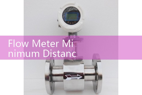
Flow Meter Minimum Distance Calculations: Preventing Valve Cavitation and Signal Distortion
Quick Answer
Install the flow meter upstream of the control valve when possible. After a valve or pump, allow 10D to 20D straight run for electromagnetic and ultrasonic meters, and 20D to 30D for vortex meters. For a DN50 line, that means 1000 mm to 1500 mm of straight pipe before the meter.
Why Valve Cavitation Breaks Flow Meter Readings
Many flow meter installations fail because the meter sits too close to a control valve. A valve creates a pressure drop. If downstream pressure falls below the fluid vapor pressure, vapor bubbles form. These bubbles collapse inside the pipe. That collapse creates shock waves and noise. The noise travels into the flow signal.
For electromagnetic flow meters, vapor bubbles act like gas pockets. The meter reads a lower or unstable conductivity path. For vortex meters, cavitation changes the vortex shedding frequency. The result is a flow reading that jumps even when actual flow is stable. For ultrasonic meters, bubbles scatter the acoustic signal. The signal can disappear for seconds at a time.
Here is the thing. The control valve does not need to be fully open or fully closed to cause problems. A valve operating at 30 to 50 percent open often creates the most cavitation in low pressure systems. We have seen this on customer sites in Vietnam, Malaysia, and Chile.
Minimum Straight Run Rules After Valves and Pumps
Minimum distance is normally expressed in pipe diameters. A 10D rule means ten times the internal diameter. For a DN50 pipe, 10D equals 500 mm. For a DN200 pipe, 10D equals 2000 mm.
The required straight run depends on the obstruction type. After a single elbow, many meters need 10D to 20D. After a partially open control valve, the flow is far less uniform. Vortex meters need 20D to 30D after a control valve. Electromagnetic meters can work at 5D to 10D in clean liquid with a full pipe. Ultrasonic clamp-on meters may need 10D to 20D upstream and 5D downstream. Coriolis meters are less sensitive to swirl but still need enough straight run to avoid severe cavitation at the sensor.
A paint manufacturer in Southeast Asia installed a vortex flow meter 6D after a globe valve. The flow signal jumped 12 percent during every batch. Silver Instruments moved the meter to 22D and installed a straightening vane. The signal stabilized.
Flow Meter Minimum Distance Calculation Formula
Use this rule in the field:
L = K x D
L is the required straight pipe length. D is the internal pipe diameter. K is the obstruction factor.
Typical K values for liquid lines:
Single elbow: K = 10 to 20. Partially open butterfly or globe valve: K = 20 to 30. Pump discharge: K = 25 to 40. Two elbows in different planes: K = 30 to 50.
If you do not have space, install a flow straightener or a conditioning plate. A straightener can reduce the required run by 50 to 60 percent. But the straightener must be placed before the meter, not after it.
Recommended Meter Types and Straight Run Limits
Silver Instruments supplies several flow meter types for these installations. For water, wastewater, and chemical dosing with conductivity above 20 µS/cm, the electromagnetic flow meter is common. Use at least 5D to 10D upstream when installed after a control valve. For steam and compressed air, a vortex flow meter often needs 20D to 30D upstream. For custody transfer
For fuels from 1 cP to 100 cP or viscous oil with low flow, oval gear flow meters do not need the same velocity profile control. They still need a strainer and enough piping to avoid cavitation at the inlet. For gas flow in small lines below 100 kg/h, thermal mass flow meters can operate with 10D upstream and 5D downstream.
Model examples from Silver Instruments:
| Meter Type | Model Series | Typical After Valve Straight Run | Signal Output |
|---|---|---|---|
| Electromagnetic flow meter | EMF series DN15 to DN3000 | 5D to 10D | 4-20 mA HART, pulse |
| Vortex flow meter | VXF series DN15 to DN300 | 20D to 30D | 4-20 mA HART, pulse |
| Ultrasonic flow meter | USF series DN15 to DN6000 | 10D to 20D | 4-20 mA, Modbus |
| Coriolis mass flow meter | CMF series DN3 to DN150 | 0D to 5D for stable flow | 4-20 mA HART, pulse |
| Oval gear flow meter | OGF series DN4 to DN80 | 0D to 5D | pulse, 4-20 mA |
Do not put a control valve immediately downstream of a positive displacement meter if the valve can cavitate. The pressure drop can damage the meter and create measurement error. Vortex and thermal mass meters can be supplied with ATEX Zone 1 certification for gas and steam skids.
FAQ: Minimum Distance and Cavitation
1. Why does a flow meter need straight run after a valve?
A valve creates swirl, jetting, and asymmetric velocity profile. The meter needs straight pipe to return the flow to a stable profile. Without straight run, the meter reports a flow rate that is not accurate.
2. Can a flow meter be installed upstream of a control valve?
Yes. Upstream installation is the better choice. The valve then controls pressure downstream. The flow meter sees liquid before the pressure drop and before cavitation bubbles appear.
3. How much straight run does a vortex flow meter need after a control valve?
Use 20D to 30D after a control valve. For a DN50 line, that equals 1000 mm to 1500 mm. Add a straightening vane if the available space is shorter.
4. Does cavitation affect magnetic flow meters?
Yes. Cavitation bubbles change the liquid conductivity path. The magnetic meter may still output a signal but the reading becomes noisy or drifts lower.
5. What information should I send for a flow meter sizing check?
Send us your pressure in bar, temperature in °C, pipe size DN, flow range, fluid name, and upstream obstruction type. Silver Instruments will calculate the minimum straight run and recommend a meter model.
Get a Straight Run Check for Your Process
If your flow meter sits near a valve, pump, or elbow, do not guess the distance. Send us your pressure in bar, temperature in °C, pipe size DN, flow range, and fluid type. We will return a minimum straight run calculation and a meter quote for your application.
Contact Silver Instruments at Tel: +86-25-68650347, WhatsApp: +86-25-52155837, WeChat: +86 15365082610. You can also visit flow-meter.com.au for product data sheets and technical notes.
 Hot Product
 Related AD