

『Flow Indicator Water Meter Installation: Visual Flow Verification for Plumbing Circuits』Related information(flow rotameter|digital flow meter|balo meter|hydraulic flow meter|volumetric meter|positive displacement meter|pitot tube flow meter|displacement meter|cfm meter|variable area flow meter|inline flow meter|differential pressure flow meter|calibrated flow meter|velocity meter|paddle wheel flow meter|oval gear flow meter|anemometer hvac|multiphase flow meter|doppler flow meter|thorpe tube flowmeter|heat flow meter)
Flow Indicator Water Meter Installation: Visual Flow Verification for Plumbing Circuits
Quick Answer: Install a flow indicator water meter in a straight pipe section after the isolation valve. Match the arrow on the body to the actual flow direction. Use bypass piping when a plumbing circuit cannot be stopped during inspection or cleaning.
Why Visual Flow Verification Matters in Plumbing Circuits
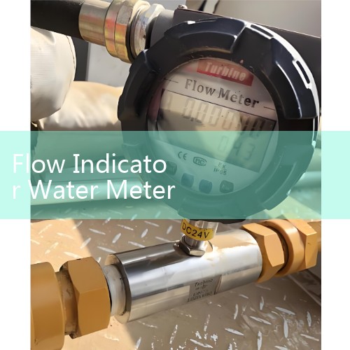
Engineers on site do not always need a 4-20 mA output. They need a direct view of water movement. A mechanical flow indicator water meter shows flow through a transparent window by rotating impeller or paddle movement. This visual flow verification for plumbing circuits helps operators spot blockages, pump shutdowns, valve failures, and filter clogging before a sensor alarm appears.
We have seen this on customer sites many times. A cooling water loop in a chemical plant in Malaysia had a faulty control valve. The inline flow indicator window showed no rotation while the control system still displayed an open valve command. That visual check saved a batch.
Installation Position and Pipe Size Selection
For DN15 to DN50 plumbing circuits, install a mechanical inline flow indicator water meter with threaded BSP or NPT ends. For DN65 and larger, use a wafer or flanged model with a transparent window or paddle pointer. Pipe size selection matters because an oversized indicator may not rotate at low flow. An undersized unit creates pressure drop.
In practice, most engineers select the same size as the pipe. For open loop cooling lines, a DN25 inline visual flow indicator with 2 to 20 L/min range works well. For filter outlet monitoring, choose the unit after the filter housing, not before it.
Mounting Orientation and Flow Arrow
Check the arrow on the instrument body. The arrow must point in the same direction as water flow. Many installation errors come from reverse mounting. For horizontal pipes, install the indicator with the viewing window on top or at 45 degrees. For vertical pipes, flow should go upward through the indicator. Gravity keeps the impeller or paddle stable.
Some clean water indicators can work in vertical downflow. Check the datasheet. Silver Automation Instruments supplies visual flow indicators for horizontal and vertical installation. Confirm orientation before ordering because internal bearing load changes.
Straight Pipe Run and Connection Details
Flow indicators for plumbing circuits do not require the same long straight run as an electromagnetic flow meter. Still, keep at least 5 pipe diameters straight before the indicator and 3 diameters after the pump outlet. This reduces swirl and gives a stable reading. For a DN25 pipe, that means 125 mm straight inlet and 75 mm outlet.
Use PTFE tape on threaded connections. Do not use too much tape. Loose tape can enter the transparent window and block impeller movement. Tighten the body by hand first. Then give one full turn with a wrench. Avoid pipe dope on plastic threads.
Pressure, Temperature, and Material Compatibility
A standard brass body flow indicator water meter suits clean water from 0 to 90°C and pressures up to PN16. For hot water circuits or chemical dosing lines, specify 316 stainless steel body and Viton seals. For feed water with sodium hypochlorite dosing, check the elastomer. A customer in Saudi Arabia replaced a brass unit with 316 stainless steel after repeated seal swelling. The root cause was not pressure, it was chemical attack.
Give us the actual pressure in bar, temperature in °C, pipe DN, and flow range in L/min or m³/h. We will match the indicator body, window material, and seal to the plumbing circuit.
Isolation Valves and Bypass Piping
Install a ball valve upstream and downstream of the flow indicator water meter. If the circuit runs 24 hours a day, add a bypass line. This allows removal of the indicator for cleaning without stopping production. For a 2 inch cooling water header in a Vietnamese seafood plant, we specified a full bore ball valve bypass around the visual flow indicator. The maintenance team now cleans the window every month without system shutdown.
Use full bore valves. Reduced bore valves create pressure drop and can cause the indicator to read lower flow.
Common Field Installation Mistakes
One mistake is mount
Most engineers skip this part. They install the indicator with the window facing a wall. Then nobody can see the visual flow verification reading. Place the window where an operator can see it from the walkway.
Plastic pipe stress also causes leaks. Support the pipe before and after the meter body. Do not let the flow indicator carry the weight of the pipe.
Step by Step Installation Procedure
Step 1: Isolate the plumbing circuit and drain pressure to zero.
Step 2: Check the flow indicator water meter for damage in the window and confirm the flow arrow direction.
Step 3: Install the meter in the pipe run with the arrow matching flow direction. Use PTFE tape or gasket as required.
Step 4: Open the upstream valve slowly. Fill the line and check for leaks at both connections.
Step 5: Open the downstream valve. Bleed air through the vent or drain point.
Step 6: Start the pump and observe the impeller or paddle for steady movement.
Step 7: Record the visual flow reading at normal operating flow and compare it with pump curve or control valve position.
Visual Flow Verification After Startup
During startup, air in the line can cause the impeller to spin unevenly. Bleed air completely. Watch the indicator at low flow for at least 30 seconds. The reading should be steady. If the impeller stops at low flow, check the minimum flow rating of the meter. Mechanical indicators have a friction threshold. A DN25 unit may not move below 2 L/min depending on water temperature and bearing type.
For circuits that need an electrical signal, pair the visual indicator with a pulse output reed switch or a compact electromagnetic flow meter. Do not rely on the visual window for recording or totalizing. Use it for fast field verification and fault finding.
Recommended Installation Package
Silver Automation Instruments supplies inline flow indicator water meters for plumbing circuits in brass, 316 stainless steel, and PVC body options. For clean cold water lines up to DN50, select a brass body with glass window and PTFE seal. For hot water or mild chemical lines up to DN50, select 316 stainless steel with tempered glass window. For larger line sizes, pair a visual flow indicator with an electromagnetic flow meter for totalized flow data.
Send us your pipe size in DN, flow range in L/min or m³/h, pressure in bar, temperature in °C, and connection type. We will send a quote with lead time and shipping to your site.
Contact Silver Automation Instruments. Tel: +86-25-68650347. WhatsApp: +86-25-52155837. WeChat: +86 15365082610. Website: flow-meter.com.au
FAQ: Flow Indicator Water Meter Installation
Can I install a flow indicator water meter in a vertical pipe?
Yes. For vertical pipes, mount the indicator with flow going upward. This keeps the impeller bearing stable and prevents reading drops during low flow. Check the minimum flow rating for vertical installation.
What is the minimum straight pipe run for a visual flow indicator?
Keep 5 pipe diameters straight before the inlet and 3 pipe diameters after the outlet. For most plumbing circuits, this is enough to reduce swirl from elbows or pumps.
How do I prevent leaks on threaded flow indicator connections?
Use PTFE tape sparingly. Wrap the male thread two or three turns. Tighten by hand and then one full turn with a wrench. Do not over tighten brass bodies on plastic pipe fittings.
What material is best for a plumbing flow indicator water meter?
Brass works for clean water up to 90°C and PN16. Use 316 stainless steel for hot water, soft water with chlorides, or chemical dosing lines. PVC is an option for low pressure corrosive water.
Does a visual flow indicator replace a flow meter?
No. A flow indicator gives local visual verification. It does not give totalized flow or continuous 4-20 mA output. For billing, dosing control, or remote monitoring, install an electromagnetic flow meter or oval gear flow meter in the same line.
 Hot Product
 Related AD