

『High Temperature Ultrasonic Flow Meter Manual: Specialized Waveguide Interfacing for Hot Pipelines』Related information(flow rotameter|digital flow meter|balo meter|hydraulic flow meter|volumetric meter|positive displacement meter|pitot tube flow meter|displacement meter|cfm meter|variable area flow meter|inline flow meter|differential pressure flow meter|calibrated flow meter|velocity meter|paddle wheel flow meter|oval gear flow meter|anemometer hvac|multiphase flow meter|doppler flow meter|thorpe tube flowmeter|heat flow meter)
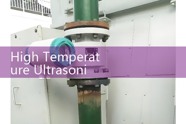
High Temperature Ultrasonic Flow Meter Manual: Specialized Waveguide Interfacing for Hot Pipelines
Quick Answer: For hot pipelines above 150 °C, a standard clamp-on ultrasonic flow meter sensor will fail or drift. A specialized waveguide interface keeps the piezo elements away from the hot pipe surface and allows reliable flow measurement up to 400 °C. Silver Automation Instruments supplies these high temperature ultrasonic flow meters with 316L stainless steel waveguides for DN50 to DN1200 pipes.
Why Standard Sensors Fail on Hot Pipelines
Standard clamp-on ultrasonic transducers have a temperature limit near 150 °C. Above this the piezo ceramic expands, the acoustic coupling dries out, and signal amplitude drops. We have seen this on a refinery line in Indonesia where the surface temperature reached 230 °C. The meter read flow for two hours and then lost signal.
Here is the thing. A hot pipe also changes the sound speed in the pipe wall. The transducer tuning frequency shifts. That is why a high temperature flow meter needs a buffer rod. The buffer rod is often called a waveguide.
Waveguide Interfacing Explained for Field Engineers
A waveguide interface is a metal buffer rod installed between the pipe surface and the ultrasonic sensor. The rod length is calculated from the pipe temperature, the ambient temperature, and the sound speed of the rod material. It moves the piezo element to a cooler zone.
On a 350 °C steam condensate line, a 150 mm long 316L stainless steel waveguide can reduce the sensor face temperature to about 80 °C. That keeps the sensor within its rated range. The waveguide is bonded or clamped to the pipe using a high temperature coupling film and a stainless steel fixture.
Installation Steps for Hot Pipeline Sites
First, clean the pipe surface on the side of the pipe. Use the 3 o clock or 9 o clock position if you face the pipe end. Do not place the waveguide at the top or bottom of a horizontal pipe. Second, measure the pipe wall thickness and verify the pipe schedule. Third, apply the high temperature coupling film. Fourth, clamp the waveguide block with a stainless steel strap or magnetic fixture. Finally, connect the transducer cable and route it away from the hot surface.
Most engineers skip the wall thickness check. On a DN150 Schedule 80 pipe in a Saudi Arabian chemical plant, a wrong wall thickness value caused a 4 percent flow error for six months.
Recommended Sensor and Transmitter Pairing
For pipe surface temperatures up to 400 °C, pair the Silver Instruments SAI-HTU-200 transmitter with the WG-316 waveguide sensor assembly. The transmitter accepts 4-20 mA HART, pulse, and RS485 Modbus outputs. The WG-316 uses a 316L stainless steel buffer rod and works on DN50 to DN1200 carbon steel, stainless steel, and duplex pipes.
For lower temperatures from 150 °C to 250 °C, the standard high temperature clam
Temperature, Pressure, and Pipe Size Limits
The waveguide interface handles liquid temperatures up to 400 °C. The pipe surface can be slightly hotter. The maximum pipe pressure depends on the pipe schedule. A DN100 Schedule 80 pipe at 350 °C typically holds more than 40 bar. The flow meter is non-intrusive and does not lower the pressure rating.
Minimum pipe size is DN50 for waveguide sensors. Maximum is DN1200 with dual path configuration. We have supplied a DN800 hot water line in Australia with a dual path waveguide set. The flow range was 200 to 6000 cubic meters per hour.
Viscosity above 100 cP can reduce signal quality. For high viscosity fluids, we suggest a larger sensor frequency or a different mounting angle.
Common Site Problems and How to Avoid Them
One problem is acoustic short circuit through the clamp fixture. Use the insulator pad supplied in the waveguide kit. Another problem is signal loss at sunset when ambient temperature drops quickly. The transmitter should be set to automatic gain control. A third problem is low flow below 0.3 meters per second. Transit time mode may need a different sensor gap.
We have seen many customer sites in Vietnam where the high temperature cable was tied to the steam pipe. That melts the jacket and causes noise. Route the cable 300 mm away from the hot surface.
FAQ
Q1. Can I mount a standard ultrasonic flow meter on a 200 °C pipe?
No. Standard sensors fail above 150 °C. Use a high temperature sensor or a waveguide interface.
Q2. Does the waveguide affect flow accuracy?
The waveguide adds a small time delay. The transmitter corrects this delay when you select the waveguide sensor type. Accuracy stays within 1 percent of reading after setup.
Q3. Which pipe materials work with a waveguide interface?
Carbon steel, 316L stainless steel, duplex, and copper nickel are common. We can tune the sensor for each pipe material before shipment.
Q4. What information do you need for a quote?
Send us the fluid type, flow range, pressure in bar, temperature in °C, pipe size DN, and pipe schedule. We will select the waveguide length and transmitter code.
Q5. Can the meter be used in ATEX Zone 1?
Yes. We supply intrinsically safe or explosion proof versions with ATEX and IECEx approval for gas and dust zones.
Contact and Quote Request
Contact Silver Automation Instruments for a high temperature ultrasonic flow meter quote. Send your pressure in bar, temperature in °C, pipe size DN, and flow range. Tel +86-25-68650347. WhatsApp +86-25-52155837. WeChat +86 15365082610. Website https://flow-meter.com.au
 Hot Blog
 Related AD