

 Current position >About Us
Heat Flow Sensors: Thermal Energy Transfer and BTU Calculation Cell Frameworks
Quick Answer: Heat flow sensors measure thermal energy transfer in heating or cooling loops. A BTU calculation cell framework converts flow rate, temperature difference, and fluid properties into kW, BTU/h, or MJ/h. Silver Automation Instruments supplies thermal mass flow meters, electromagnetic flow meters, and matched temperature sensors for DN15 to DN400 process lines.
This page gives engineers a practical selection route for heat flow sensors and BTU meters. We cover what the sensor measures, how the BTU calculation cell works, and what to send us for a quote.
What a Heat Flow Sensor Actually Measures
A heat flow sensor does not measure thermal energy directly in most systems. It measures flow and temperature difference. The calculation cell integrates these signals over time. For water and water glycol loops, two matched PT100 or PT1000 sensors measure supply and return temperature. A flow meter measures volume or mass flow. The cell applies the formula Q = m x cp x delta T.
In practice, most engineers skip the integration step and buy a packaged BTU meter. The packaged meter includes the flow sensor, a pair of temperature probes, and a calculator unit. The output is direct energy flow in kW or BTU/h.
We have seen this on customer sites many times. A plant will install a flow meter and two temperature probes. Then they realize the PLC must handle all math. That adds engineering time. A packaged BTU meter saves that step.
The BTU Calculation Cell Framework in Practical Terms
The calculation cell reads flow signal, temperature difference, and fluid data. For water at 60 °C, the specific heat capacity is about 4.18 kJ/(kg·K). A flow of 20 m3/h with a 10 K temperature difference gives roughly 232 kW thermal power.
Most industrial BTU calculators store density and specific heat tables for water, water glycol, and sometimes thermal oil. The cell compensates for temperature changes every few seconds. It outputs energy flow, totalized energy, and often pulse for billing.
Silver Automation Instruments offers a calculation cell with 4-20 mA HART, Modbus RTU, and pulse outputs. It accepts flow inputs from electromagnetic, ultrasonic, or vortex meters. This gives engineers flexibility on large pipes.
Why Thermal Mass Flow Meters Fit Heat Flow Applications
For gas and air thermal energy, a thermal mass flow meter measures mass flow directly. No separate pressure and temperature compensation is needed. This design suits natural gas, compressed air, biogas, and flare gas lines.
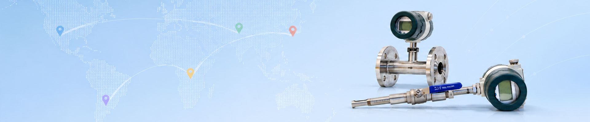
A typical inline thermal mass flow meter from Silver Automation Instruments covers DN15 to DN300. It handles flow from about 0.5 kg/h on small lines. Accuracy is plus or minus 1.5 percent of reading for many gas ranges. Output includes 4-20 mA HART and Modbus RTU. For hazardous zones, insertion probes can be ordered with ATEX Zone 1 certification.
For liquid heating and cooling loops, a thermal mass flow meter is not the right tool. Use an electromagnetic flow meter and matched RTD pair. The BTU calculation cell then provides the heat flow data.
Key Inputs for Accurate BTU Calculation
Engineers need the correct fluid type and glycol concentration. A 40 percent propylene glycol mix has a different specific heat than pure water. If the wrong fluid table is selected, energy total can drift 3 to 5 percent.
Inlet and outlet temperature sensors must be matched class A PT100 or PT1000. Mount the supply sensor and return sensor close to the flow meter. For liquid lines, the flow meter needs a full pipe. For electromagnetic flow meters, fluid conductivity should be at least 5 µS/cm. This covers most water, wastewater, and water glycol mixes. For thermal oil or low conductivity fluids, tell us early. We may recommend a different flow elem